After the Wuhan Petrochemical Water Flow Standard Equipment (hereinafter referred to as the “Equipmentâ€) was built and operated in 2005, it has undergone many company-wide overhauls and successfully completed the verification of the flowmeter. With the completion of the second phase of the company's refining project and the ethylene project in Wuhan, the tasks that the company is undertaking are also increasing. In recent years, some technical problems appearing in this device have become increasingly prominent, such as the inability of partial mass flowmeter signals to be received and the commutator time difference measurement method to be flawed. Some problems have affected the verification of the device. In 2014, I stationed the facility to renovate, which not only solved related technical issues and regulatory compliance issues, but also improved the degree of automation of flow meter verification. 2.2 The efficiency of large tanks to affect the efficiency of the test water release rate 6t large tanks slow water, sometimes up to 8min, in the flow meter intensive inspection regular, such as the maintenance period is a problem. According to the JJG1038-2008 Coriolis mass flowmeter verification procedures, if a DN150 mass flowmeter is used to test the large tank, under normal circumstances, 1 table shall verify 5 flow points, and each flow point shall have a verification frequency of not less than 3 Secondly, 15 times of water is needed. The time for water discharge is more than 100 minutes. If the flow meter verification process is not smooth, the flow time for one meter will be too long. Visible discharge speed has affected the work efficiency. The diameter of the original 6t weighing vessel (large tank) under the drain pipe and the waterproof pneumatic valve is DN150. The original drainage pipe was removed and replaced with DN250 pipe and pneumatic valve. The drainage time was reduced to about 1 minute for the above DN150. The flow meter is calibrated, saving about 1 hour compared to the previous time, which solves the problem of the efficiency of the water discharge speed. Table 1 in the DN25 commutator swapped in, swapped out Class A relative standard uncertainty S5 is 0.0010663, S6 is 0.0007621, Class B relative standard uncertainty u4 is -0.00322. From the above table, it is known that the stability of the crystal oscillator for 8 hours is not lower than the uncertainty of the device, and the requirements of Section 3.3.3 of the procedures are met. After the transformation of the device, the Hubei Provincial Bureau of Technical Supervision conducted the verification of the device. The verification results are as follows: Sewage flow meter Recirculating water flow meter Tap water flow meter Electromagnetic flow meter Smart electromagnetic flow meter A crankshaft, also called crank,is a mechanical part able to perform a conversion between reciprocating motion and rotational motion. In a reciprocating engine, it translates reciprocating motion of the piston into rotational motion; whereas in a reciprocating compressor, it converts the rotational motion into reciprocating motion.Sonora Motors can supply scooter crankshaft for GY6 engine,AM6 minarelli engine,Yamaha YBR125,Suzuki AX100,and for scooters of Jonway, Longjia,Znen,Baotian,Wangye. Vespa PX125 Crankshaft,Aprilia Am6 Crankshaft,CMG50 Puch Crankshaft SONORA MOTOR COMPANY , https://www.sonoramotor.com
1. Introduction to the original device
1.1 Technical parameters The device uses water as the calibration medium, from the groundwater pool, pump system, regulator gas system, 6 flow meters, flow regulators, 6 calibration table, 4 sets of weighing systems, frequency control systems and automatic Control system and other components. The diameter of the flow meter that can be verified is from DN15 to DN200, and the flow rate is from 0.5 to 500 m3/h. The device can use the static mass method (primary standard), the standard form method (transfer standard) and volumetric method to verify the flowmeter. Types of detectable flowmeters include Coriolis mass flowmeters, turbine flowmeters, vortex flowmeters, electromagnetic flowmeters, ultrasonic flowmeters, liquid displacement flowmeters, cold water meters, and the like.
1.2 Workflow The static mass method is used as an example. After the device is powered on, the water pump pumps water from the water tank into the surge tank, and after the filter is replaced, it enters the tank or bypass pipe through the valve, standard table, or inspection table. After the process is opened and before the test is started, a selected tank bottom valve is started to be checked, that is, the linkage commutator will send the water to the tank, and at the same time, the signal of the check table will be collected. After the water level in the tank reaches a certain height, the direction will be reversed. When the switch is switched to the bypass valve, the collection of the signal of the meter under inspection and the reading of the electronic scale are stopped, and the verification error is calculated to form a data table. The original device flow chart shown in Figure 1.
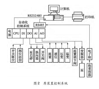
1.3 Control System Introduction The control system is used to collect the output signals of standard flowmeters, temperature sensors, pressure sensors, electronic balances, and detected flowmeters and sensors on the processing equipment, and to complete the flow switch valve, flow control valve, pump, etc. on the device. The control operation completes the flow meter verification control process. The original device control system is shown in Figure 2.
2. Existing problems and countermeasures of the original device
2.1 The Stability of Water Quality Impact Assessment Since the completion of the 2005 impact assessment, the device has not opened up the sewage pipeline, resulting in the verification of the water has not been replaced, after the annual verification, the pool of oil sludge, the oil containing oil, and the smell of odor, but also affect The physical health of the certified personnel. According to the JJG164-2000 liquid flow standard device calibration procedure 3.1, "The liquid shall be single-phase clean water or other liquid with a kinematic viscosity not exceeding 35 × 10-6 m2/s." I stationed the pipelines that were missing from the device's sewage pipelines and opened them up, smoothly drained the wastewater to the factory's oily sewage system, and then cleared the pool and added 150m3 of fresh water to the pool. This not only eliminated the odor, but also solved the problem. Verify stability issues. 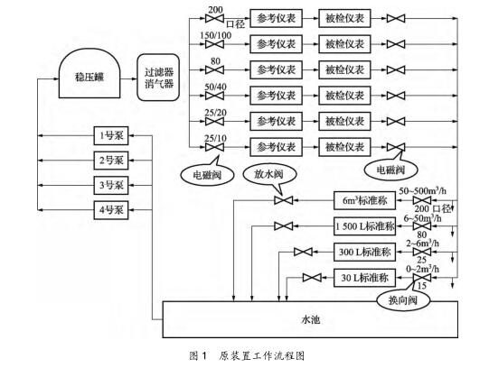
2.3 Exhaust filter corrosion serious, excessive pressure loss problem During the use of the original device, the elimination filter is heavily rusted, the exhaust pipe leaks, and the pressure loss is too large, reaching 0.1 MPa. As shown in Fig. 1, there is one pressure change display pressure between the surge tank and the getter filter, and the indicator value of the indicator pressure gauge at the detected flow meter is 0.1 MPa different, and the pressure required for the flow meter is 0.2 MPa. affected. Considering that the upstream regulator tank has an exhaust function, the degassing filter was dismantled and the outlet of the regulator tank was directly connected to the calibration table pipeline by pipeline. After demolition, the pressure displayed by pressure change is 0.005 MPa different from the pressure displayed on the pressure gauge, which greatly reduces the pressure loss.
2.4 Problems with Some Meters
(1) The six devices on the six pipelines of the original device had no return signal, and the status of the valve on the control program screen was unclear. This modification introduced the valve signal into the verification program, which made the valve control screen more intuitive and solved the problem.
(2) The original device uses an external 24, 12 and 5 VDC power supply for the flow meter and does not use the power output of the control cabinet. This transformation will direct the DC power supply in the control cabinet to the verification station, which can directly supply power to the transmitter. Select whether to power the transmitter in the program.
(3) The original device has the problem that the pulse signal output by the mass flow meter produced by some manufacturers is unstable or unreceivable and affects the normal verification of the flow meter. The F8601A pulse shaping module was rebuilt and installed to realize the normal reception of pulse signals of all types of mass flowmeters used by Wuhan Petrochemical and Wuhan Ethylene.
2.5 Commutator replacement and exchange time difference measurement method is defective The commutator is an important part of the device. According to the liquid flow standard device verification procedures, the commutator uncertainty (s2, u2) participates in the device synthesis uncertainty. The calculation of u directly affects the measurement accuracy of the device. Therefore, the commutator verification is an important task in device verification.
According to the JJG164-2000 liquid flow standard device verification procedures 5.2 article and test methods under the verification method 5.2.7 commutator verification flow meter verification method and differential method. Since the device was not installed with a stroke signal switch at the beginning of the installation, only the flow meter verification method can be used. This method is complicated. According to the regulations, at least 10 commutation must be performed in each commutator verification, and at least 10 verifications are required. One commutator must be commutated at least 100 times, and four commutators must be commutated at least 400 times. In addition, in addition to the weighing device, the cumulative reading of the weighing device can be directly read. Due to a defect in the programming of the program, the accumulated pulse number of the flow meter and the accumulated measurement time cannot be correctly determined. This measurement method cannot be performed in practice.
In this modification, 4 sets of commutator synchronization devices were added, and a TGC-10 type photoelectric pulse signal converter and a baffle for detecting the commutation time was installed on the commutator. The converter was an open type photoelectric conversion device. When the baffle reaches the infrared Light hole in the converter's open slot, it sends a signal.
After the modification of the device, the commutator time difference measurement is performed using a simpler method of difference in travel. According to the regulations, each commutator only needs to switch 10 times under the verification flow, and after calculating the time average of swap-in and swap-out, substituting the procedure formulas (19)-(21) into the equation A can be calculated. Standard Uncertainty and Class B Relative Standard Uncertainty. At the same time, the installation of the photoelectric transmitter takes into account both the commutator verification and the synchronization of the quality method. When verifying the device, each commutator is equipped with a baffle with two racks to measure the exchange in and out. At the time of checking the flowmeter, each commutator only needs to install a rack gear, and cooperates with the pneumatic valve to control the amount of water entering the tank.
Table 1 shows the record of the time difference of the DN25 commutator after retrofitting. 
It can be seen that the method for determining the time difference of the commutator after modification is not only more in line with the requirements of the regulations, but also the method for determining the time difference of the commutator change-out and switching in is more convenient and time-saving.
2.6 No external time measurement unit problem The original system does not have an external time measurement unit. According to the JJG164-2000 liquid flow standard device verification procedure, the device crystal oscillator (time metering) must be included in the verification. External time measurement unit equipment needs to be added.
The TH102 type high-precision timer was retrofitted to provide the basic clock signal to the system. The time measurement was introduced into the quality method verification and comparison method verification synchronous control, so that the system software has time measurement, high-speed pulse measurement unit verification function. After the transformation, the device is more in line with the requirements of the regulations. The stability of the crystal oscillator (2014-10-31) for 8 hours is shown in Table 2. 
2.7 The original program manual calculation of many tasks The transformation of the use of the GEPLCPACSystemsRx3i, PLC programming using ProficyMachineEdition7.5, the host computer programming software for the Kingview. Added functions such as automatic calculation of verification time, automatic transmission of instrument parameters to output forms, etc. in the verification software.
Removed the task of manual calculation and repeated input of instrument parameters.
3, before and after the transformation of the device after transformation, and the original device, such as shown in Table 3. 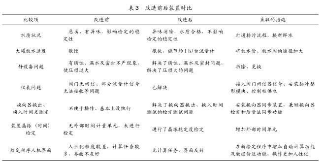
The extended uncertainty of the device: the standard table (group) method is better than 0.2%; the static mass method is better than 0.05%; the static volume method is better than 0.05%.
Flow stability: better than 0.2%.
Solution to Some Problems of Water Flow Standard Equipment